Folding @ Quarantined Home

Recently, Bridge Fusion Systems acquired two modestly equipped server machines to beef up the local network infrastructure at the office.  They are in the process of being configured for this purpose, but in the meantime we’ve found an interesting use for them, in response to the current global pandemic due to COVID-19. You don’t have to have a server machine to participate in this effort. Some of Bridge Fusion Systems’ employees have also joined the effort with their personal computing hardware. The PC or Mac that you have sitting around most of the time can participate too.

I first heard about distributed computing probably in college, now some two-digit years ago.  Normally, a computer executes programs locally for its own user(s). With distributed computing projects, donors volunteer computing time from personal computers to a specific cause.  SETI@Home was the first project of this kind that really popularized this genre in a viable way, launched in May 1999.  It provided a mechanism for distributed computers to collaboratively search radio signals from space for signs of alien intelligence.  I think I fired up a SETI@Home client for a few weeks before losing interest.

In a more recent incarnation of distributed computing (by about 1.5 years), Folding@Home has risen in popularity due to its contributions to efforts in modeling the COVID-19 virus and its protein interactions.  When the project maintainers announced this effort to combat the coronavirus, the public quickly mobilized behind the project.  We at Bridge Fusion heard this call, and the following is the documentation of our efforts to put our servers to use in this way.

Folding@Home Headless Installation

Setting up Folding@Home on a computer with a Graphical User Interface (GUI) is usually rather straightforward.  Download the program, run it, complete the installation wizard, and you're good to go.  However, the server machines are running a "headless" operating system, which means they have no GUI.  That said, the Folding@Home documents made this pretty easy too.  I created a new container on one of the servers, and ran the following commands:

wget https://download.foldingathome.org/releases/public/release/fahclient/debian-stable-64bit/v7.5/fahclient_7.5.1_amd64.deb
dpkg -i --force-depends fahclient_7.5.1_amd64.deb

At this point, the Folding@Home (F@H) client was running, waiting to receive a Work Unit (WU) from one of the central coordinator servers.  The F@H client provides an interface to its controls and status via a web service, hosted by the client itself.  However, the default behavior of the client is to only allow access to its control page from the local machine.  This presents a difficulty for a machine without a GUI!  To allow access to the control page from another computer, the F@H client's config.xml file had to be changed.

First, stop the F@H Client:

systemctl stop FAHClient

Then, edit the config file:

vi /etc/fahclient/config.xml

I changed the 'allow' and 'web-allow' tags to allow access from any IP address (any other computer on the same network):

<config>
  <!-- Folding Slot Configuration ->
  <gpu v='false'/>

  <!-- HTTP Server ->
  <allow v='0/0'/>
  
  <!-- Slot Control ->
  <power v='full'/>
  
  <!-- User Information ->
  <team v='243174'/>  
  <user v='BFS_fah1'/>  

  <!-- Web Server ->  
  <web-allow v='0/0'/>  

  <!-- Folding Slots ->  
  <slot id='0' type='CPU'/></config>

Then, restart the client:

systemctl start FAHClient

And now, we have control!  The client's control page is accessible from a URL constructed using either the machine's hostname or IP address.  With a machine name of "folding1", we can access it here:

http://folding1.bfs.lan:7396

And a pretty picture to prove it:

If you want to join Bridge Fusion Systems’ team, use team number 243174.  Happy folding!

Some advanced setup

Well, we do have two servers, so the next step I took was to clone the container holding the F@H Client and migrate it to the other server.  With Proxmox, this is very easy:

Access to the web interface still seemed a little clunky to me (who wants to remember port 7396?).  So, I went the extra mile and created a reverse HTTP proxy to provide a nice, user-friendly URL to access the page from.  I fired up another container in Proxmox to provide a reverse proxy service to forward connections as follows:

  http://fah1.bfs.lan  =>  http://folding1.bfs.lan:7396

I installed nginx in the container:

  apt install nginx

Then got the reverse proxy up and running using the following configuration file:

  vi /etc/nginx/sites-available/fah1.bfs.lan

Contents:

server {
  listen 80;
  listen [::]:80;

  server_name fah1.bfs.lan;

  location / {
     proxy_pass http://folding1.bfs.lan:7396;
     proxy_set_header Host $host;
   }
}

I also copied this file to provide proxy service for the second Folding@Home instance on the other server (fah2.bfs.lan).

Test and reload the nginx configuration:

nginx -t
nginx -s reload

One final step:  Create an alias for "fah1" and “fah2” in our DNS Resolver to point to the reverse proxy IP address.  Here at BFS, we use pfSense for this task:

Now, we can access the control/status pages via:

http://fah1.bfs.lan
http://fah2.bfs.lan

Final Notes

●     CAUTION:  The configuration above will allow any computer on your network to change settings for your client.  Our folding client is on a local network, and we trust everyone here to not mess with it.

●     I think there are configuration settings for requiring a password to change client settings, but it may also restrict viewing the client status as well.

●     Normally, you’d want a reverse proxy to provide SSL service, and even redirect HTTP requests to HTTPS, but for this example it would require more effort than we wanted to put into it (LetsEncrypt certificates, more complex proxy configuration, etc).

Robot Localization -- Calibration

    In this world, nothing is perfect.  However, we can get pretty close to perfection.  Thus, another important part of building the dead reckoning system was calibration, getting as close to perfection as possible.  During our testing of the dead reckoner and robot driver, we noticed that our linear drives were missing the target by 5-8%. We dug into the math and double checked all of our values for robot and wheel dimensions.  Nevertheless, the issue still persisted. There are two likely sources for this error: slight imperfections in the drive train, or the effective diameter of the wheels is different since the robot drives on a foam tile floor.  To fix these problems, we added a calibration value for linear distances in the form of a simple multiplier for the amount of encoder counts per inch.

driveWheelDistancePerCount = (driveWheelCircumfrence / driveWheelCountsPerRev) * driveWheelCalibration;

    This multiplier was determined by driving a known distance and dividing that value by the distance that the robot thought that it traveled.  To accomplish this, we mounted a downward facing color sensor to the bottom of the robot and applied two tape lines to the field. (40 5/16" [40.3125] from leading edge to leading edge;  40 1/2" [40.5000] from trailing edge to trailing edge.) We placed the robot outside of these lines then drove over both of them in a straight line.

RobotCalibration.png

    We then collected the data, determined the calibration factor, and tested the results.  After the calibration, the linear drives were within a 1-2% error of their target: an exceptional level of precision for our application.

Ron L

I’m the high school engineering intern at Bridge Fusion Systems. I have also been a member of the First Tech Challenge (FTC) robotics team Terabytes #4149

TTC Streetcar Testers: A Lesson In Pair Programming

Unproductive Software Engineering Coops?

Unproductive Software Engineering Coops?

This past spring, I took a class called Software Quality Assurance. My professor, Mr. Laboon, had one primary focus throughout the semester: encourage us to create the highest quality software possible. One of the techniques that I was introduced to was the idea of “pair programming,” or in other words, having two programmers sit down in front of one machine and program together to solve a problem. I was intrigued by this idea, and throughout the class, I had a handful of opportunities to take that approach to complete the assignments.

After spring classes ended, I quickly transitioned into my second co-op rotation with Bridge Fusion Systems. Along with myself as a returning co-op, two new co-ops joined the Bridge Fusion Systems team: Erin Welling, a second rotation Electrical Engineering Co-op, and Nick Wilke, a first rotation Computer Science Co-op.

Bridge Fusion Systems specializes in embedded systems, which requires a combination of knowledge in both hardware (e.g. electrical circuits)  and software (e.g. programming in C/C++ and the paradigms involved with these kinds of applications). Having gone through my first co-op rotation here at Bridge Fusion Systems, I had first-hand experience with the questions and struggles of embedded systems: how do I flip a GPIO pin to high or low? What does pull up / pull down mean? Why do embedded programs run in a main while(1) loop? Why are there watchdogs within the system? Why are there so many state machines?

Putting myself back into the mindset of embedded after a long semester of Ruby programming, I was reminded of these struggles. Additionally, with Nick being a first-rotation co-op, having no prior embedded programming experience, this sounded like the perfect testing grounds for a pair programming experience. I brought this idea up to Andy during a one-on-one, and he was thrilled with the idea. Within a few days, Nick and I became a programming pair.

The project that we were assigned to work on was the Toronto Transportation Commission (TTC) Tester units. In Toronto, there is a streetcar system with a legacy switch control system fully implemented. Each streetcar emits a special signal that is picked up by loops in the track. Unfortunately, the devices that they use to ensure the streetcar is emitting a correct signal are no longer functional. Bridge Fusion Systems has been working for the past few months to build replacement hardware that is compatible with the legacy system already in place.

The Initial Benefits of Pair Programming

The first aspect of the testers that we worked on was the logging system. Since the TTC Testers are based on existing software and hardware, the testers use the same logging modules as the RTP-110. The RTP-110 writes log information to an SPI flash chip, which supports page-granularity when erasing data.  These chips have become obsolete. The replacement flash chips used in the TTC Testers, however, only support sector-granularity for erasing data. This was a known problem months before pair programming had begun, and for the most part, the underlying drivers were already modified during my first co-op rotation. However, the algorithm in place did not support partial log dumps, a feature that was previously requested by the customer. Because the drivers underneath the logging module were changed, the logging functionality of the entire system was broken when Nick joined the project.

AtBoard-Orig-750x412.png

Nick and I, using existing code written by Andy and Elliott, led development for the algorithm itself. My skills came into use when we wanted to take this algorithm, and split it up into an embedded paradigm that would work in the existing architecture of the TTC Tester codebase.

What was immediately refreshing to me was having another set of eyes looking at my code - and a quick pair, at that, since Nick is able to read code fairly quickly (at least faster than I am!). Once we both jumped into working on the logging system, we both realized how confusing this aspect of the program was. Originally there were two modules, named FormatDataLogging.c and DataLogging.c, many of which had functions that produced similar or identical outcomes. Sometimes, a function in DataLogging.c would call a FormatDataLogging.c function and vice versa. There was no coherent organization to these modules, and this made understanding the code a bit more difficult to do. With my newly found love for refactoring, Nick and I adjusted the code to make a lot more sense: there were three distinct modules to our logging system: BufferDataLogging.c, responsible for log entries coming into the battery-backed buffers of the system; FormatDataLogging.c, previously held the responsibility of BufferDataLogging.c, but now strictly deals with the formatting of log entries, down to the byte granularity; DataLogging.c, actually deals with permanently writing the log entry bytes to NVData / SPIFlash.

For Nick, the restructuring of the logging modules served as a good introduction to the architecture of the TTC Tester code. One of the first questions I recall from this experience was how we actually test and see whether or not our code is doing what we think it is. In embedded, many processor components interact in real time, in such a way that pausing the debugger and viewing the current state of the code doesn’t reflect what may actually be happening. DMA, for example, will continue to run even if the processor halts.

The takeaway: Once you’re comfortable in a project, it makes it a lot harder to see the flaws in said project’s organization. Throwing an outsider into the project, especially as a pair programmer, help with seeing things that a person familiar with the project would overlook.

How A Person Codes

One of the things that I noticed from the beginning was a fundamental difference in priority when it came to how Nick and I write code: Nick is very good at whipping code up quickly to get something done. He’s able to grasp the elements of the code quickly and figure out how everything works together immediately, albeit with some early struggles with embedded program structure.

However, I focus on the “fit” of the code that I’m writing, along with the “fit” of the code that’s already there. My philosophy when writing code is simple: code shouldn’t be a struggle to read. I should be able to look at it and understand what is going on, at least at a basic level. The original RTP-110 code follows a coherent code standard, but there were elements of the code where the complexity of the problem obscured the function of the code. When I’m working in an embedded systems codebase, I tend to refactor as I’m going along, just to make the naming of variables and functions clearer. For example, I’ll name functions such that they include the module name so I know where within the project they come from.

After the first few weeks, Nick became the “what” guy: Here’s what we have to do, and here’s how we could do it. I was the “why” guy: thinking more about the consequences of code changes, how our code changes can affect anything else in the program, and generally cleaning up or refactoring the code to make it easier to read and modify. When it came to making the adjustments for the logging system as a whole, this dynamic worked well.

The takeaway: Pair programming with different types and ideologies of programmers seems to work well-- knowing how to code and the consequences of your code is important.

Knowing When To Pair

The logging system in the TTC Testers was the primary reason that pair programming began within this project. However, once that component of the project was complete, there were other changes that needed to be made; arguably, for some of these changes, they didn’t necessitate the same amount of attention or require the same amount of time. Ultimately, it wasn’t the best approach to do the traditional pair programming techniques for these tasks. Instead, Nick and I would split up the work that needed to be done, and focus on finishing parts of the task at hand, on our own hardware, and then pair program the merged changes on one machine, just to make sure none of our changes would break the program.

Generally speaking, this was a good approach when it needed to be done, but it requires having people who recognize that pair programming isn’t the best approach for the particular scenario. For example, power manager and serial menu code were two aspects of the project that we could easily split up some of the tasks without stomping on each other, but ultimately, when we wanted to make sure that the changes we made would merge well together without conflict, that’s when we went back to the pair programming ideology. Perhaps this is also where my fatal flaw came into play: I have a strong desire to make code clean and readable, which means a lot of voluntary refactoring on my part (I swear, Nick thinks refactoring is my new favorite word).

The other good thing about kinda having the pair programming option hovering above our heads was that it kept us on track, even when Nick and I were having rough days focusing. As what Nick refers to as “bringing the ruckus”, there were days where one of us or both of us couldn’t quite focus on the work in front of us, and ultimately, might have spent a little bit too much time goofing off. But, at the same time, as a pair we were also able to police each other and keep each other on track. In a way, whether or not we were directly pair programming, just having the second person to keep me accountable for my work helped make me a bit more efficient in the tasks that were at hand.

The takeaway: Not every situation is a pair programming situation. But, having the option and knowing when to use it is a valuable tool. Simply being in a pair programming environment also helps keep each other on track for the tasks at hand.

Someone’s causing ruckus (Hint: it’s me!). Would this be considered a probe attack?

Someone’s causing ruckus (Hint: it’s me!). Would this be considered a probe attack?

The Hardware Could Be Wrong!

Most software engineering co-ops don’t really like touching hardware--I’m a weird exception to that rule myself. In software land, we assume that the hardware is there and functional for us, and we need to do everything we can from the software side to make things work. We rarely like to blame hardware-- But, in reality, hardware isn’t always right. And after a few days of struggling with power manager code, we learned this the hard way.

Before we received actual tester board hardware, we were running our firmware on older RTP-110 control boards. Since these boards didn’t have a power manager hardware built into them, we used a ST Microelectronics Nucleo Evaluation board to emulate the power manager. Additionally, since we were updating code on both the power manager and the control board, we didn’t want our OpenOCD debugger to confuse which device we actually wanted to debug to: so ultimately, we opted to use a USB wall outlet power brick. Except there was a weird problem: the Nucleo board would only run code on the STM32 processor if it was plugged into a USB port on a computer.

Given Nick and my lack of hardware knowledge, we deferred the problem to Andy, who is a bit more knowledgeable in hardware land. Andy came to the initial conclusion that we “probably” have a hardware problem, and thus, we should focus our programming efforts on trying to figure out why this was acting wonky. Additionally, it was the last functioning Nucleo board that we had in the office at the time, so there was no other hardware that we can test or compare against.

The jumper above the USB port was missing!

The jumper above the USB port was missing!

Nick and I tried adjusting the configurations for the board, but to no avail. After spending a day or two attempting to debug this behavior, Sean eventually made his way around and was able to bring in another Nucleo board to try out. On his Nucleo board, however, the code would run just fine when the board was powered through a USB wall outlet power brick.

As it turns out, there was a very minor hardware difference between the two boards, in the form of a missing jumper.

The takeaway: Pair programming can’t solve hardware problems.

Hardware that *isn’t* safe for Software Engineers!

This was probably one of the points where Nick struggled the most. Unfortunately, Nick didn’t have the best track record for keeping the micros alive. Enough so, that in the office, we created a counter for the days since our last dead micro.

You’ll notice that it in this photo, the counter is in the double digits-- only because we finally finished the project.

You’ll notice that it in this photo, the counter is in the double digits-- only because we finally finished the project.

You’ll notice that it in this photo, the counter is in the double digits-- only because we finally finished the project.

There were various reasons why we fried micros-- mostly because of our own carelessness, (e.g. from not being careful with the mess of wires we had on our desk and accidentally shorting 12V or -18V to 3.3V). Nonetheless, the careless mistakes that we made cost us, especially when it came down to production time, because at points, Nick and I were relying on each other’s hardware.

In this particular scenario, blowing up our own hardware actually helped us find a relatively serious bug, that could potentially cause an end user to blow up a micro. In other words, blowing up hardware on our own, from what Nick and I believed to be our own mistakes, led us to finding an actual hardware problem that could have sporadically and catastrophically destroyed hardware.

Nick seemed to be blowing up one particular board repeatedly. Andy originally blamed this on something that Nick must have been unaware of doing; that was, until Sean was using one of the production units for testing transmitter wands and had the same failure. In this case, Nick was nowhere near the hardware when it happened. More investigation by Sean uncovered the scenario that happened occasionally and would have happened to the end user. A fix was implemented in hardware to prevent damage to the unit, and a secondary fix was additionally added in software to help make the problem even less likely. As it turns out, that particular failure wasn’t really Nick’s fault!

Likewise, having a pair that really didn’t understand hardware made it even more worthwhile to place a focus on making our hardware “safe” for software engineers, as best as we could. In other words, don’t create a setup that could cause a disaster: keep track of your stray wires, and make sure they aren’t in a position to short higher voltages into 3.3V. Setups like these kept ourselves from destroying hardware left and right:

The takeaway: Take some time to sit down and know what the heck you’re doing, hardware wise, so that you don’t blow up hardware. If it means adjusting the hardware so that it’s harder to blow up, do it.

Putting Trust in the Overhead of Pair Programming

In our situation, Nick and I were in the perfect position to pair program. Nick previously had experience building software, and I had prior experience in embedded from my last co-op rotation. Compared to the rest of our team at Bridge Fusion Systems, Nick and I were really the closest in terms of time and experience within the field of Computer Science generally; thus, I think that helped me anticipate the things that Nick wouldn’t have known walking in to the world of embedded--after all, I was in Nick’s shoes less than a year ago, not really knowing my own footings in embedded land.

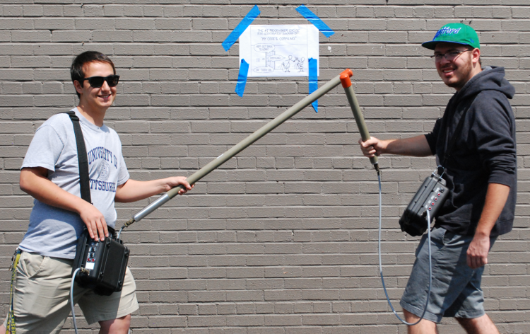
I’m still shocked that we spent company resources on printing out an XKCD meme, going to the effort to tape it to the wall, then grabbing the Testers and posing in front of the meme in the same pose as those in the picture, and taking a photo. Actua…

I’m still shocked that we spent company resources on printing out an XKCD meme, going to the effort to tape it to the wall, then grabbing the Testers and posing in front of the meme in the same pose as those in the picture, and taking a photo. Actually, it’s glorious and is a perfect example of the Bridge Fusion Systems culture… Eh, we have fun!

I think many reasons why companies tend to steer away towards pair programming is the idea of losing efficiency in regards to the amount of code that can be produced, or adding unnecessary overhead to the development process. And through Nick and I’s experience, I’ve developed a bit of a counterargument to this thought. There were many times where Nick and I got into discussions and/or even arguments over what the best approach was for implementing a feature or segment of code, and from the perspective of an outsider, that looks like wasted time. But in reality, it’s not: even if our discussions regarding the best implementation for code are seemingly pointless in the moment, learning the different methodologies and consequences of those methodologies helps us as embedded programmers in the long run. I constantly have to remind myself when working in embedded that the entirety of the program is tied together so closely, and so a change that I make in one portion of the code can have drastic effects on any other part of the code. How code is implemented in the world of embedded really matters in this kind of programming environment, and sometimes, the “overhead cost” of pair programming can really be worth it in the long run. I’m glad I had the opportunity to try this programming approach in en embedded environment at Bridge Fusion.

The takeaway: Pair program!


Robot Localization -- Driving to Field Coordinates

My FTC team was tired of programming autonomous programs using a string of distance drives; if you needed to make an adjustment, you needed to redo all of them.  Bill Gates once said, “I choose a lazy person to do a hard job. Because a lazy person will find an easy way to do it.” Thus, we decided to use our laziness as motivation to build a program that made our programming lives easier. Throughout the season our team developed a dead reckoner (see previous post) and a robot driver that drives the robot to any specified location on the field. That way, if we made an adjustment, it only affects the target point that we changed. This post addresses how our “robot driver” works.

After the dead reckoner is initialized, you can enable the robot driver.  To begin driving, you simply add waypoints to the queue and specify how long you want to take to get to each waypoint.  A waypoint contains a field relative (X, Y) coordinate, a time budget to get to that waypoint, a time type (“FromNow” or “FromLastWaypoint”), and an id number.  Once the queue contains waypoints, the motion will begin. The robot driver then calculates the X and Y error that the robot needs to drive from the current position supplied by the dead reckoner.  Then, based on the time budget specified by the user, the robotDriver increments an instantaneous waypoint along the desired path until the robot reaches the destination.

InstantaneousWaypoints.png

    The advantage of using a string of instantaneous waypoints over a single waypoint is that the robot will drive back onto the specified path if it drifts off of that path.  Had we used a single waypoint, the robot would simply take the shortest path from where it is; if the robot drifts off path, it then will take the shortest distance from there.  This presents a problem if you are driving near obstacles. If the robot is close to an obstacle and it drifts, it may try to drive through the obstacle instead of driving on the specified path.  Since there are structures in the middle of the field, it was imperative that the robot stayed on the specified path. Thus, driving by a string of instantaneous waypoints was the best option. In addition, speed control is accomplished by controlling the rate at which the instantaneous waypoint moves along the specified path.

Code Sample:

//Grab the time now
drivingCurrentTime = DSPTimeBased.getNowSeconds();
//Figure out the elapsed time
drivingElapsedTime = drivingCurrentTime - movePlannedStartTime;
//Compute the next instantaneous position
tempInstCoord = (Coordinate.CoordinateType.TerabyteF,
xVel * drivingElapsedTime + startOfDriveCoordinate.getX(),
yVel * drivingElapsedTime + startOfDriveCoordinate.getY(),
rotVel * drivingElapsedTime + startOfDriveCoordinate.getThetaRAD());
//See if we're done with this move: 
//we're basing this entirely on elapsed time
if(drivingElapsedTime >= movePlannedTimeDelta)
{
    //We're done.  Go back to idle
    state = States.Idle;
    //Make sure we didn't over drive the end 
    //point by just using the end coord.
    tempInstCoord = targetWaypoint.getCoord();
    //See if we were waiting to notify of reaching this waypoint
    if(targetWaypoint.getId() == this.waypointIDForTrigger)
    {
        this.waypointTriggered = true;
    }
}
instantaneousCoordinate = tempInstCoord;

The instantaneous waypoint calculated by the robot driver is sent to the position controller.  The position controller’s job, is to drive the robot to the instantaneous waypoint calculated by the robot driver.  This is accomplished by driving the error to zero using velocities generated by two PI controllers; one in the X direction and one in the Y direction.  Then, by harnessing the power of triangles, we use those velocities to calculate a velocity vector (magnitude and direction) which is then rotated onto the robot’s reference frame.  Robot rotation is controlled similarly using a PI controller to drive the rotational error to zero.

    robotErrorTheta = fieldErrorTheta - robotTheta;
FieldVsRobot-ErrorTheta.png

Position Controller Code:

//We need to pre-compute the error value for 
//the rotational axis because it's strange 
//and loops around.
rotFieldError = (fieldTargetPosition.getThetaRAD() -
    FieldFeedbackPosition.getThetaRAD() + 20.0 * Math.PI) % 
    (2.0 * Math.PI);
if(rotFieldError > Math.PI)
{
    rotFieldError -= 2.0*Math.PI;
}
//Compute the controllers for the three 
//degrees of freedom, in field frame reference.
xFieldVel = this.xController.processInput(
                fieldTargetPosition.getX(),
                fieldFeedbackPosition.getX());
yFieldVel = this.yController.processInput(
                fieldTargetPosition.getY(), 
                fieldFeedbackPosition.getY());
rotFieldVel = this.rotController.processInput(
                rotFieldError,
                0.0);  //Use the rotational error in place
//Get the error terms back because we need 
//them for other checking
xFieldError = this.xController.getError();
yFieldError = this.yController.getError();
//Move these velocities onto the robot frame of reference
//-Magnitude is the same in field frame as in robot frame
linearVelMagnitude = Math.sqrt(
                       xFieldVel * xFieldVel + 
                       yFieldVel * yFieldVel);
//-Find the angle of the velocity 
// command vector and subtract the robot angle
linearVelTheta = Math.atan2(
                       yFieldVel, 
                       xFieldVel) -
                 fieldFeedbackPosition.getThetaRAD();
//Rotational is rotational
rotaionalVelMagnitude = rotFieldVel;

Finally the position controller sends the calculated magnitude and direction to the holonomic drive code which moves the robot.  The holonomic drive calculates speeds for each wheel by taking the specified velocity vector and calculating its components along the angular direction that each wheel drives at.

HolonomicDrive.PNG

Holonomic Drive Code:

controlsToSpeed(Mag, thetaDEG, r)
{
    rotConst = 0.75;
    Theta1 = (thetaDEG - 45);//Front Left
    Theta2 = (thetaDEG + 45);//Front Right
    Theta3 = (thetaDEG + 135);//Back Right
    Theta4 = (thetaDEG - 135);//Back Left
    Theta1 = Math.toRadians(Theta1);
    Theta2 = Math.toRadians(Theta2);
    Theta3 = Math.toRadians(Theta3);
    Theta4 = Math.toRadians(Theta4);
    vector1 = Mag * Math.cos(Theta1) + (r*rotConst);
    vector2 = Mag * Math.cos(Theta2) + (r*rotConst);
    vector3 = Mag * Math.cos(Theta3) + (r*rotConst);
    vector4 = Mag * Math.cos(Theta4) + (r*rotConst);
    mag1 = Range.clip(vector1, -1, 1);
    mag2 = Range.clip(vector2, -1, 1);
    mag3 = Range.clip(vector3, -1, 1);
    mag4 = Range.clip(vector4, -1, 1);
}

Upon arriving at a waypoint, the robotDriver then moves on to the next waypoint in the queue.  If the queue is empty, the robot driver reports that the motion is complete and the position controller holds the robot’s position on the field.  When we tried to manually push the robot, it responded with a satisfying stubbornness: it pushed back!!

Below is a control diagram for the dead reckoning system, as it was first documented.

IMG_0569.JPG

With our dead reckoner and robot driver in place, our autonomous programming lives became significantly easier.  We could reliably develop and test entire autonomous programs in as little as 20-30 minutes (compared to 4-6 hours before).  Therefore, one of the best skills of a programmer is building code that makes his/her life easier.

Ron L

I’m the high school engineering intern at Bridge Fusion Systems. I have also been a member of the First Tech Challenge (FTC) robotics team Terabytes #4149

Obsessed with Major Transportation Accidents?

If you’ve talked to me at certain times, you may have had me talk your ear off about some transportation accident, usually that’s had loss of life.  I’ve probably told you about news I’ve read, maybe ad nauseum. If it was an older one, I may have sent you a link to an NTSB report.  And no, it’s not really for this reason.

One factor in my obsession is certainly the loss of life.  These kind of engineering, system-engineering, management, human factors engineering failures cause the most pain to the people closest to those who died.  As a secondary effect, consider the engineers and technicians that did work, or who’s failure to do work, that may have been a contributing factor; those people may carry guilt about an accident for the rest of their lives.

Bridge Fusion Systems has done work that supports rail transportation.  Some of the work we’ve done, like the RTP-110 switch controller for the Toronto Transportation Commission, gets very close to being safety critical.  

Fortunately, none of the work we’ve done has ever been a factor in any transportation accident. But, every time there is one of these accidents I am compelled to understand the failures in the process that led to it so that we can learn from it.

We tell debugging stories.  Some people might find them boring.  The point of their telling is to pass along important information about how defects manifested themselves.  Sometimes, the point is how our own blindness to what the system was trying to tell us made it harder to fix the problem.  In all cases, the meaning of this story is to prevent others from repeating our same mistakes, to gain experience second-hand.

Following the reporting or NTSB report from an accident is like hearing a very large, usually sad debugging story.  The stories sometimes cover more than just technical details: Management practices, behavior and communication among technicians and other human factors such as distraction are also included.

From these, I want to have clear ideas in my head about how things go wrong: technical, leadership, focus, distraction and confusion.  Like the debugging stories, I want to have ideas in my head, in the heads of the people who work for me, of how what we do might lead to failures that could be serious.  I want to be able to recognize these paths to failure at the circuit, software, system and leadership level.

Thinking this way has affected the way we build our products and recommend products be built for our customers, even when they’re not safety critical.  For instance, data logging within the product, data logging of everything that’s practical has helped us find subtle bugs before they turned into customer and end user complaints that would have been hard to track down.  

If you want to read more about some of the incidents that have affected our thinking, you could start here:

EDIT: Apr 16, 2019: I’ve fixed a badly phrased sentence above and added below some events that I’ve heard have influenced people I know and respect.

Robot Localization -- Dead Reckoning in First Tech Challenge (FTC)

A note from Andy: Ron is a high school intern for us. I’ve known him for several years through the robotics team that I mentor. He’s been the programmer for the team. Here, he gets to share a thing that he did that made autonomous driving of the robot much, much easier.

During the past several years, I have been a part of FIRST Tech Challenge, a middle school through high school robotics program.  Each year a new game is released that is played on a 12ft X 12ft playing field. Each team builds a robot to complete the various game tasks.  The game starts off with a 30 second autonomous (computer controlled) period followed by a 2 minute driver-controlled (“teleop”) period. This post addresses robot drive control during the autonomous period.

In my experience on the team, autonomous drive was always somewhat difficult to get to work right.  It was normally accomplished by something like driving X encoder counts to the left, turn Y degrees, then drive Z encoder counts to the right.  Any additional movements were added on top of this kind of initial drive. One of the major disadvantages of this method is that when you adjust any one linear drive or turn, you then have to change all of the following drives that are built on top of the drive you adjusted.  We began to think, “wouldn’t it be nice if we could just tell the robot ‘go to (X, Y)’ and then it went there all on its own.” This all seemed impossible, but this past year, our dreams (which might be the same as yours) began to come true.

In years past, FIRST (the head organization) had implemented Vuforia in its SDK.  The SDK is basic software we are required to use. Vuforia is machine vision for smartphones that enables localization.  Vuforia would identify vision targets on the field walls and then report back the location of the camera relative to the target.  The location of the robot could then be determined with some matrix math.

However, we found that Vuforia was only able to get an accurate reading on the targets while the camera was within 48 inches of the target.  See the image below to get an idea of how much of the field is excluded from useful Vuforia position information.
Since we are frequently well out of range of the vision targets, Vuforia was not the solution to our problem.

Then, we considered using the drive wheel encoders.  Based off of the robot’s initial position we would track the encoder deltas and compute the live location of the robot.  Our initial concern with this idea was that the wheels would slip and cause the robot to lose knowledge of its location.  This would make the use of encoders for localization useless.  Thus, our dreams remained crushed like mashed potatoes.  But when all hope seemed lost, in came an inspiration: we could use the encoders to track the location, and then calibrate that location when we get a Vuforia reading.  With this in mind, we began work on encoder based localization software, which we call a dead reckoner.

The initial step in development was to record the encoder values from a drive around the field.  We would then be able to use this data for the development of our math, checking it against a video of the drive.

This is the video of the drive that goes with that initial data collection:

For scale in the video, note that the tiles on the field are 24 inches square, shown by the jagged edged grid.

After much hard work, we developed an algorithm that uses the encoder deltas to track the robot’s location.  This is a plot (with a scale in inches) of the computed location of the robot over that drive:

ComputedPosition.png

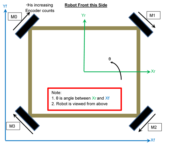
Before we describe the algorithm, we need to define a coordinate system for the robot and the field and the robot. Here is a diagram of the robot and its wheel locations and a picture so that you can see where the wheels are located and how we’ve defined axes for the robot and the field.

RobotGeometryDefinitions.png

The math for the dead reckoner is implemented within a Java method that is called, with new encoder values, on every pass through the opmode’s loop() method.  The final math for the system using a four-wheel omni drive is as follows:

//Compute change in encoder positions
delt_m0 = wheel0Pos - lastM0;
delt_m1 = wheel1Pos - lastM1;
delt_m2 = wheel2Pos - lastM2;
delt_m3 = wheel3Pos - lastM3;
//Compute displacements for each wheel
displ_m0 = delt_m0 * wheelDisplacePerEncoderCount;
displ_m1 = delt_m1 * wheelDisplacePerEncoderCount;
displ_m2 = delt_m2 * wheelDisplacePerEncoderCount;
displ_m3 = delt_m3 * wheelDisplacePerEncoderCount;
//Compute the average displacement in order to untangle rotation from displacement
displ_average = (displ_m0 + displ_m1 + displ_m2 + displ_m3) / 4.0;
//Compute the component of the wheel displacements that yield robot displacement
dev_m0 = displ_m0 - displ_average;
dev_m1 = displ_m1 - displ_average;
dev_m2 = displ_m2 - displ_average;
dev_m3 = displ_m3 - displ_average;
//Compute the displacement of the holonomic drive, in robot reference frame
delt_Xr = (dev_m0 + dev_m1 - dev_m2 - dev_m3) / twoSqrtTwo; 
delt_Yr = (dev_m0 - dev_m1 - dev_m2 + dev_m3) / twoSqrtTwo; 
//Move this holonomic displacement from robot to field frame of reference
robotTheta = IMU_ThetaRAD;
sinTheta = sin(robotTheta);
cosTheta = cos(robotTheta);
delt_Xf = delt_Xr * cosTheta - delt_Yr * sinTheta;
delt_Yf = delt_Yr * cosTheta + delt_Xr * sinTheta;
//Update the position
X = lastX + delt_Xf;
Y = lastY + delt_Yf;
Theta = robotTheta;
lastM0 = wheel0Pos;
lastM1 = wheel1Pos;
lastM2 = wheel2Pos;
lastM3 = wheel3Pos;

After we got the initial math working, we continued with our testing.  All seemed to work well until we turned the robot.  After turning the robot, the robot’s heading, Θ, wasn’t calculated correctly.  Thus, when we drove after turning the robot, the dead reckoner though we were going in one direction instead of the actual direction we were driving in.  We then recorded dead reckoner and IMU data from a simple 360-degree turn, without any driving forward.  We found that as we approached 180 degrees, the error between the reckoner and the IMU grew as large as 16 degrees.

AngleErrorOverTime.png

After searching through the code, we were unable to find a solution. In order to make the reckoner useful for completion, we band-aided the system by using the IMU heading.  This solved our problems for the most part.  Everything worked properly except when you turned and drove at the same time.  It appears that the issue is due to a time delay between the IMU and encoder values.

After we had finished the Dead Reckoner, we built a robot driver that uses the robot’s position to drive the robot to a specific location on the field.  If you string together multiple points, you can accomplish a fully autonomous drive around the field as seen in this video:

The accuracy of this system, was roughly within 1 inch.

With this type of robot drive, programming autonomous drives is almost effortless.  Now all you say is “go there”, and it goes there.  No more telling the robot “go this far then that far” and then reprogramming that all over again when you need to adjust distances.  For example, the above drive around the entire field was programmed in less than 2 minutes; under the traditional method, it would take 10 minutes to do it right.  If any adjustments to your distances are needed the traditional method could take as long as 20 minutes.

Future fixes and wish list items for this code include:

  • Find the source of the angular rotation error so that we can use the encoders without requiring IMU (we should be able to do this)

  • Determine if there is a time-delay between IMU and wheel encoders reading so that the IMU can be used as a comparison to help detect errors in the wheel motion.

Ron L

I’m the high school engineering intern at Bridge Fusion Systems. I have also been a member of the First Tech Challenge (FTC) robotics team Terabytes #4149

1-Introduction

Why a blog?

Bridge Fusion Systems has existed, survived and thrived for over 11 years without a blog.  Heck, we’ve gone that long without anything that could be called even an outline of a cloud of a sales and marketing strategy.  No strategy or even any regularity or discipline, for that matter is the way we had been finding business.

Bridge Fusion Systems was founded with the idea that “landscape view” is what you need to build high quality systems that interact with the physical world.  That big picture isn’t enough; you also need to be able to control the details along the way.  When you’re building a system that “just turns a motor, reads a sensor and has some buttons an a display” there’s a myriad of ways to whip up some pieces to do that.  Each of those ways have different cost, development time and project risk tradeoffs.  Paying attention to how to put a system together to meet the customer’s needs and then being able to do that needs attention that covers the area from mechanical to software and user interface.

In short, for the last 11 years we’ve been down in the weeds, trying to do the right things for our customers to get their right product built, their right problems fixed for the right cost on the right schedule.

So, why the blog? 

My plan for this blog is that we pull the curtain back a little on the kinds of things that we do here.  One of the primary uses I see for it is in demonstrating how we take things apart to figure out what’s inside.  And by “what’s inside” I mean hardware, electronics, software, data structures and communication protocols.  The things that we can take apart in public will likely not be any of our client’s products, at least to any level of useful detail, unless they ask us to take them apart for you like that.

We can disassemble a myriad of other things that land in our laps.  I mentor a First Tech Challenge robotics team.  There are a bunch of controls topics that I’ve tried to teach them.  I’m planning on having one of my interns who is a team alumnus explain some cool things we did this year.

The 11 year sales & marketing drought and this re-irrigation of it reflects another aspect of Bridge Fusion Systems.  I’ve been accused of saying that our goal here in our work is “…to be iteratively less stupid”.  I’ll avoid using some cliché like “continuous improvement” because the truth is that it’s hard emotionally, time-allocation-aly, to reflect on what you’ve done and what you should do differently and then figure out what you can change without breaking the working parts.  We try to do that kind of self reflection at the design and project level.  We’re starting to do that at the business level.